IELS2031 Buck converter, 5 V to 1 V
Design, simulation, build and test of a synchronous buck converter in the course IELS2031 Electronics Design at NTNU. Group project of two.
The task
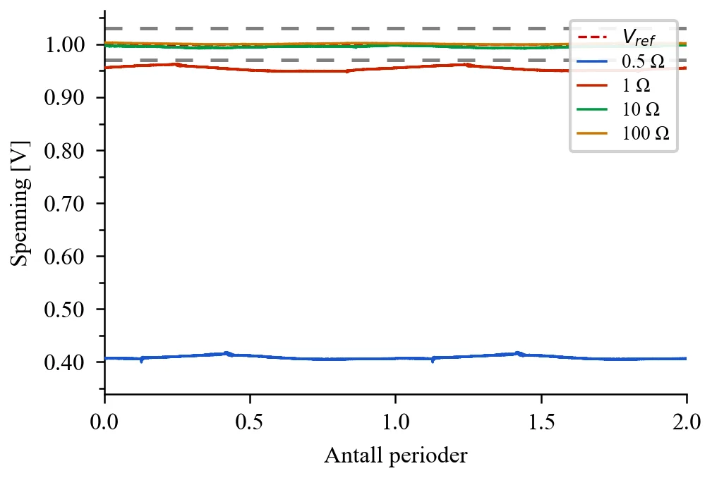
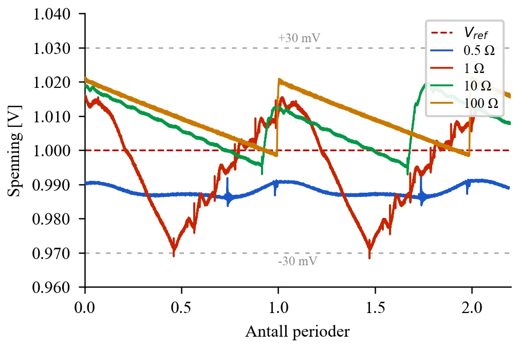
Regulate a 5 V input down to 1 V, with the output voltage within ±30 mV and ripple within ±30 mV. The requirements apply to four loads: 0.5, 1, 10 and 100 ohm, that is load currents from 10 mA to 2 A.
The circuit is built around the LTC3807, a synchronous buck controller from Analog Devices, with a switching frequency of 350 kHz.
Revision 1 and debugging
The first revision worked at light load, but the output voltage collapsed to around 0.4 V at the 0.5 ohm load. The measurements did not match the calculations, so the fault was most likely in the implementation, not in the dimensioning.
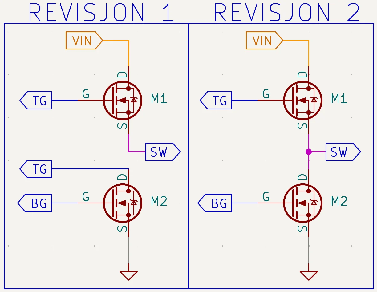
Reviewing the layout, we found a wiring error between the gate of the top MOSFET and the drain of the bottom MOSFET. It prevented correct control of the switch node, and the current went through the body diodes instead, which causes large losses at high current.
Revision 2
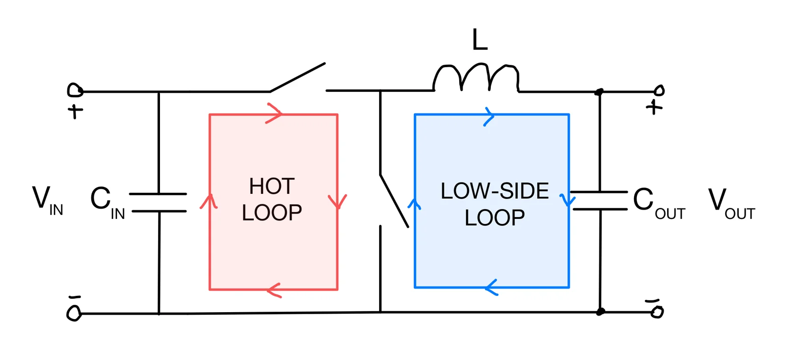
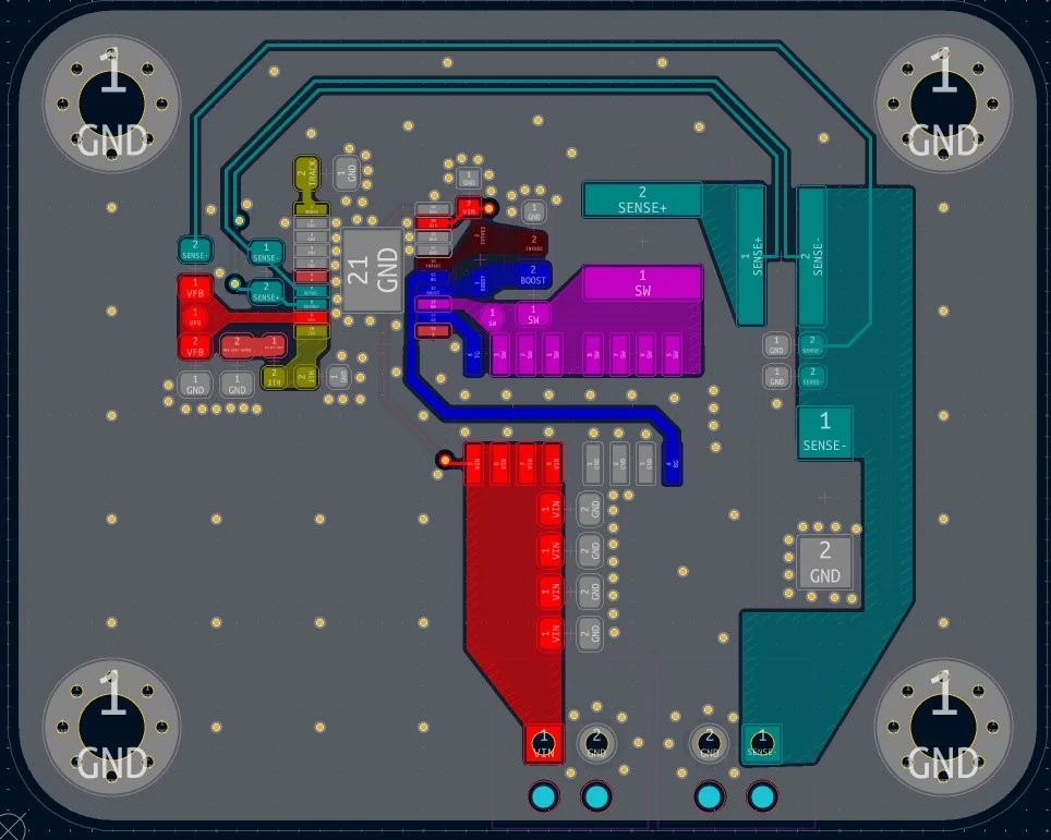
The layout was redrawn in KiCad with the correct wiring, a compact hot loop and better return currents. Component values were also adjusted for more margin: inductor 4.7 µH, output capacitor 220 µF and sense resistor 4 mΩ.
- All four loads meet both the voltage requirement and the ripple requirement
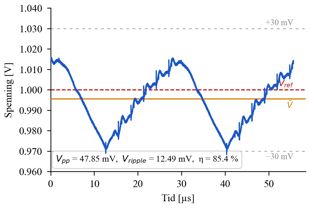
- Measured ripple (Vpp/2) between 4.5 and 23.9 mV
- Highest efficiency 85.4 % at 1 ohm
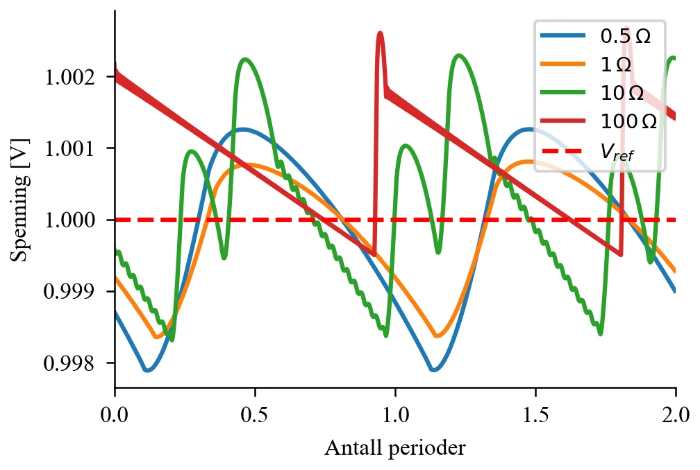
- The gap between simulated and measured ripple is partly due to Burst Mode and parasitic effects not included in the simulation
What I take with me
- Correct MOSFET wiring, a compact layout and control of the current loops decide whether a switching regulator works in practice
- Testing against calculations and simulation makes it possible to tell layout errors from dimensioning errors
- Iterating over two PCB revisions, from diagnosis to validation
Figures